Finite Element Analysis (FEA)
Structural finite element analysis to prove that a design is strong, stiff and stable enough — before it is built, lifted or certified.
We build finite element models of steel structures, machine components, lifting equipment and assemblies and use them to answer concrete engineering questions: will it hold, where is it at its limit, and what is the simplest change that makes it pass. Every model is checked against hand calculations and engineering judgement, because a colorful stress plot is only as good as its boundary conditions.
Choosing the right level of detail is a large part of the job. For bolted and welded connections we select between solid, shell, beam, joint and spring representations depending on what the verification needs — detailed local modelling where stresses matter and simplified connectors elsewhere, which keeps results accurate and run times short.
Results are reported against the acceptance criteria you need, including Eurocode, DNV, EN 13155 and ISO 19901-5 where applicable, in a report your certifying body or client can follow.
What we analyze
- Linear and nonlinear static stress analysis
- Modal and harmonic analysis (natural frequencies, resonance)
- Linear (eigenvalue) and geometrically nonlinear buckling with imperfections
- Bolted connection modelling with pretension, contact and bearing loads
- Weld modelling strategies for strength and fatigue assessment
- Solid, shell and beam element models validated against hand calculations
What you receive
- Technical report with assumptions, boundary conditions, load cases and results
- Pass / fail verification against the agreed acceptance criteria or standard
- Clear design recommendations when a component is at or beyond its limits
Finite Element Analysis (FEA) case studies
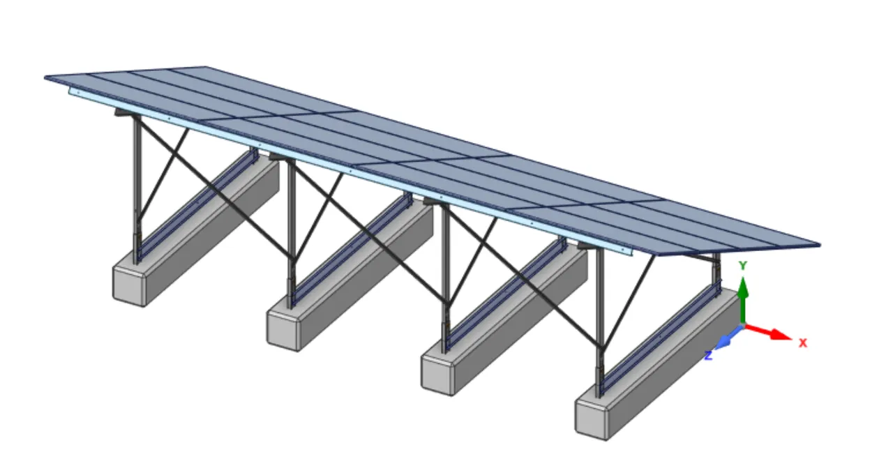
Solar Panel Structure
Eurocode verification and redesign of a steel framework supporting a ground-mounted solar panel installation.
Read case study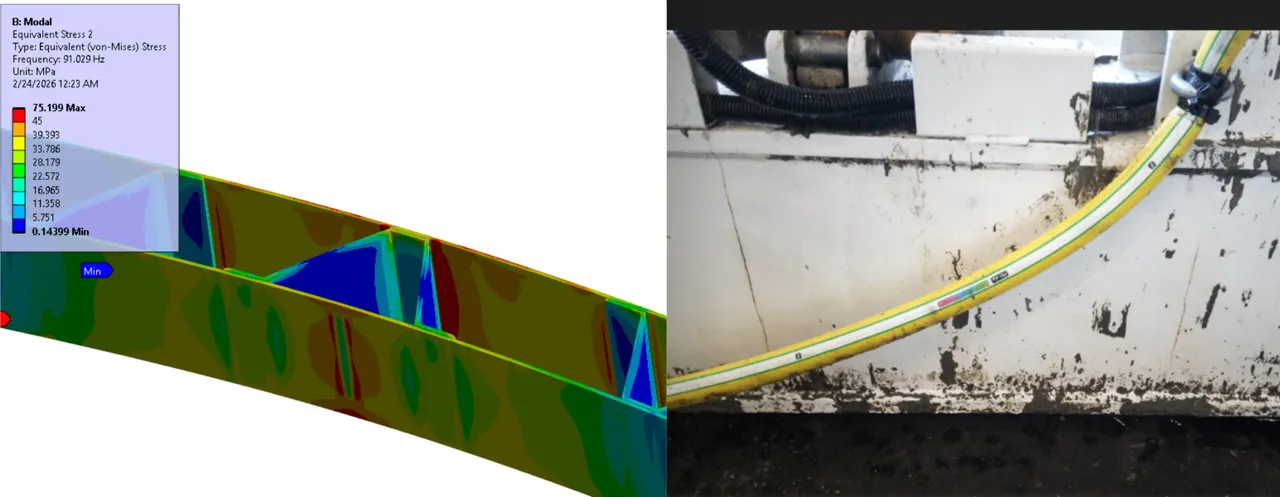
Leveling Beam
Root-cause investigation of a cracked concrete leveling beam: vibrator frequencies were exciting the beam's natural frequency.
Read case study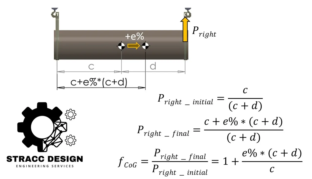
Rigging Safety Verification
Verification of a custom lifting configuration where center-of-gravity uncertainty drove sling forces, aligned with ISO 19901-5.
Read case study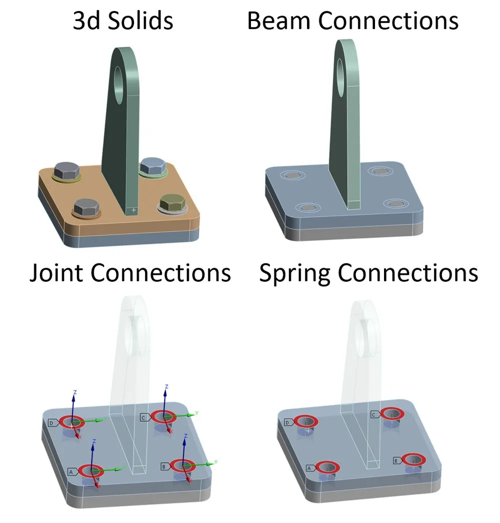
Advanced Modelling for Bolted Connections
Comparison of solid, beam, joint and spring bolt models to verify bolted lifting connections accurately and quickly.
Read case study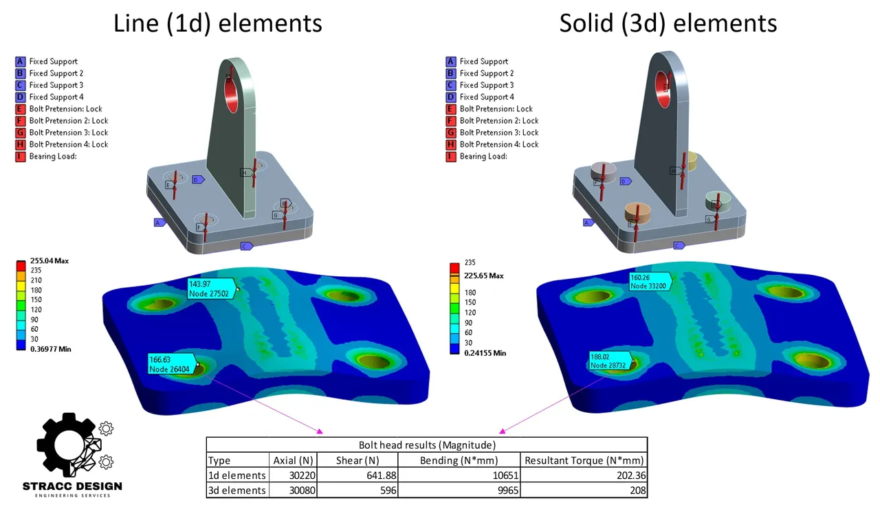
Comparative Bolt Modelling Verification
Side-by-side FEA study of 1D beam bolts versus 3D solid bolts under identical pretension and bearing loads.
Read case study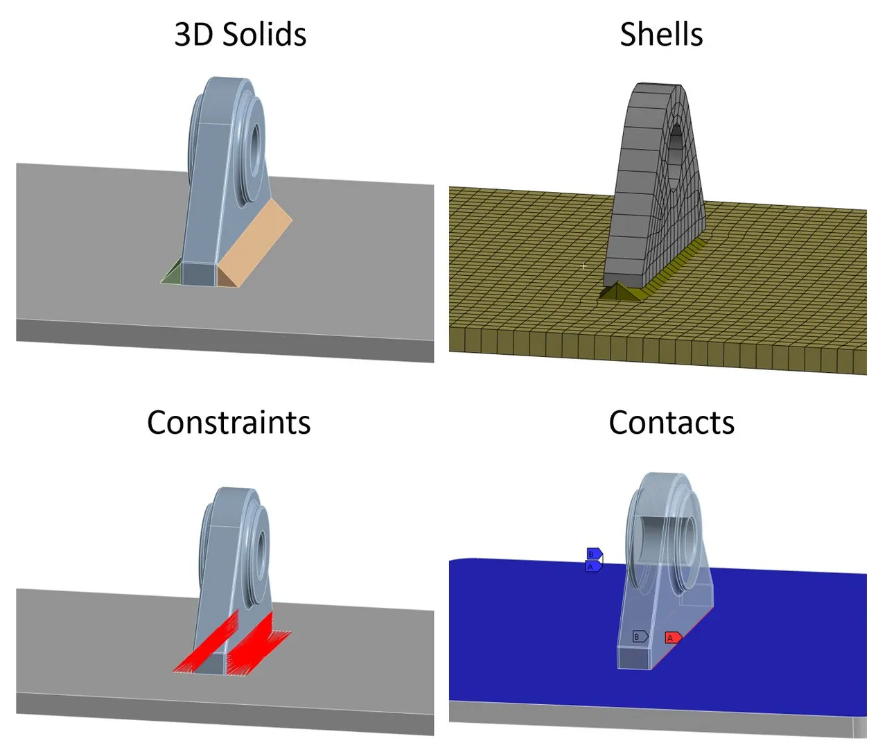
Weld Modelling Strategy
Selecting the right weld modelling method — solids, shells, constraints or contacts — for realistic load paths and fatigue stresses.
Read case study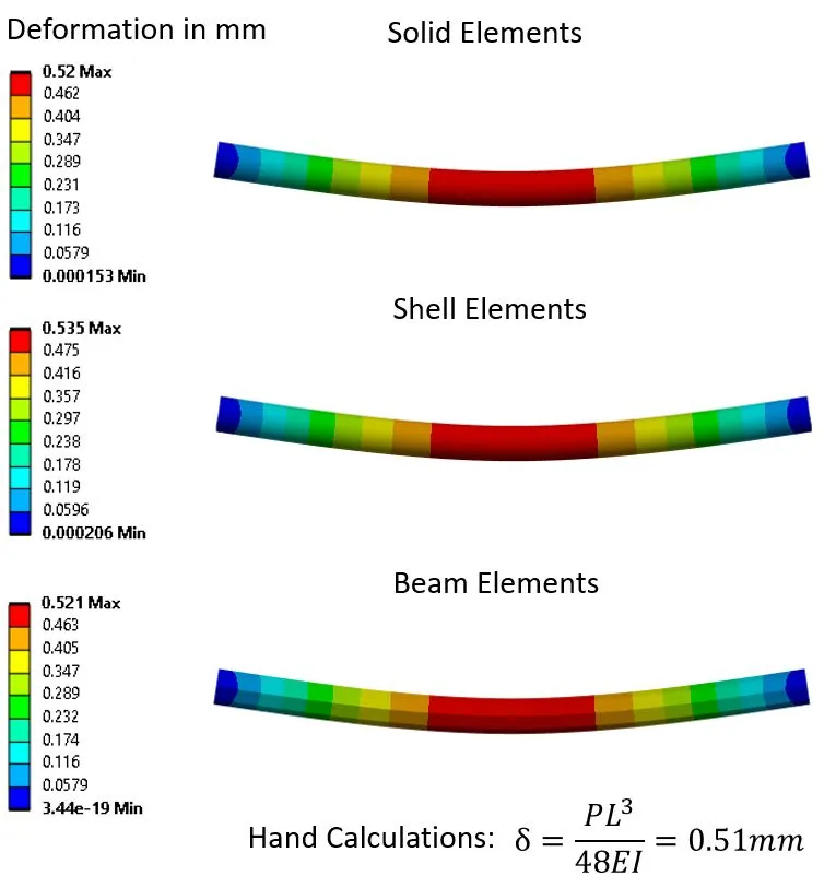
Comparative Structural Analysis
Validation of solid, shell and beam element results against hand calculations under identical loading.
Read case study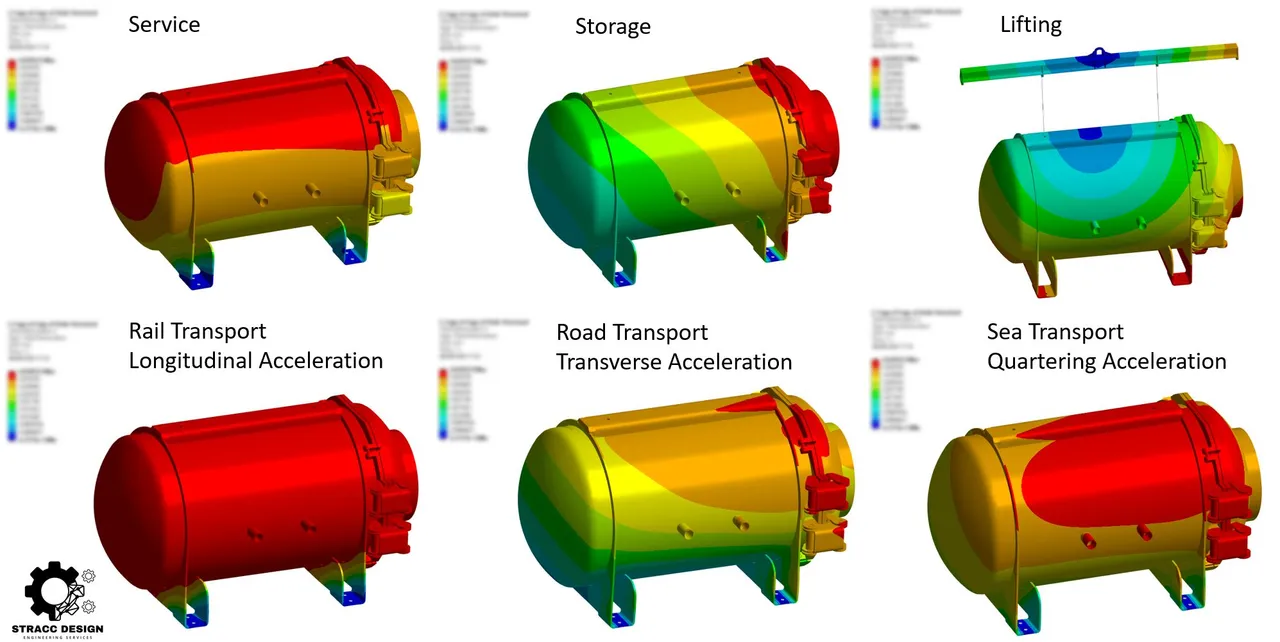
Multi-Scenario Transport & Lifting Verification
Service, storage, lifting and rail, road and sea transport load cases for heavy equipment under Eurocode and DNV.
Read case study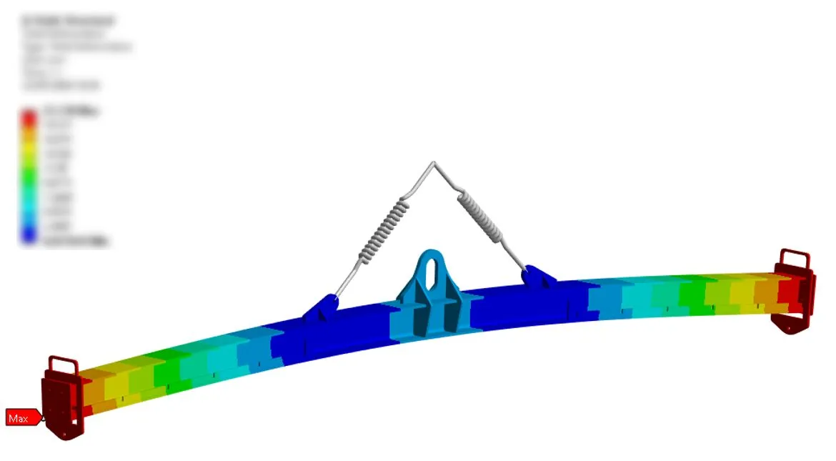
Accelerated Certification Support
Rigging calculations and FEA of custom lifting equipment against EN 13155, DNV and the Machinery Directive on a tight deadline.
Read case study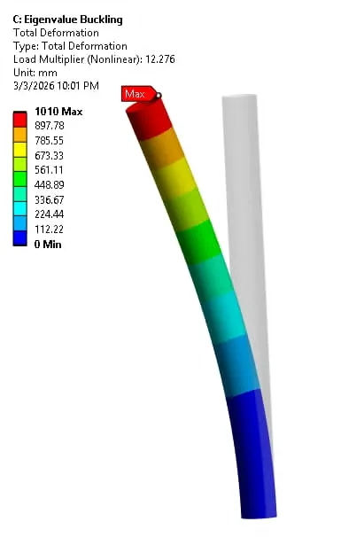
Linear & Nonlinear Buckling Verification
Eigenvalue and geometrically nonlinear buckling analysis with imperfections to find the true stability margin of a compression member.
Read case study